Build the true experience
Chapter 6
Your guide to the true experience in a home theater installation.
Your guide to the true experience in a home theater installation.
More and more people, either professional installers or even end users are becoming aware of the importance of Room Acoustics to achieve high quality sound playback.
However, it does not necessarily mean that they are ready to accept the constraints of a proper acoustic design of their Home Theater room, especially if it is not a dedicated room, but a multipurpose one.
My approach here is certainly not to teach the art of persuasion, but instead to give you an overview of what Room Acoustics is and what to consider.
Note: If you don’t want to go into technical matters, you can skip to 3.
Sound is a succession of fast variations of the air pressure. We are not considering here day-to-day meteorological variations, but very short ones, lasting less than 2/20 second.
The amplitude of these variations can be as small as 0.0002 microBars (corresponding to 1dB) to 6 Bars (corresponding to 130dB – the instantaneous threshold of pain).
You have certainly noticed that the ratio is 30,000 and not 130.
This means that the scale is not linear. Actually, it is logarithmic.
Now, these variations are typically audible only if their duration is comprised between 1/20 second and 1/20,000 second. Again, we have a logarithmic scale.
Typically, natural sounds are of a random nature. This historically made it quite difficult to study them, until a mathematician, Mr. Fourier, demonstrated that any random sound (or-by extension- signal) was made up of a combination of sinusoidal sounds of a periodic nature, each one having a fixed frequency.
He further derived a formula called the “Fourier Transform” that allows us to convert a deviation of the air pressure with respect to time into a function of the frequency:
The Fourier Transform is:

It is very convenient that this formula is reversible, meaning that you can shift from the time domain to the frequency domain, and back.
Even more convenient nowadays is that this transform is now integrated in most acoustical analysis applications. This makes life easier...
One other most important characteristic of sound is that it travels. To illustrate how this happens, just imagine a tiny sphere floating in the air (well, this is like in a Harry Potter movie).
Now, further imagine that this little sphere is pulsating, that is alternatively increasing and decreasing in volume, at a rate comprised between 20 and 20,000 pulses per second.
Over a very short period of time, when the sphere expands it will push and very briefly compress the air that is immediately around it. Likewise, when it shrinks it will decrease the pressure of the air around it.
To illustrate this, we can assume that the air - instead of a continuous medium - is a series of concentric spherical layers around the pulsating sphere, a bit like an onion.
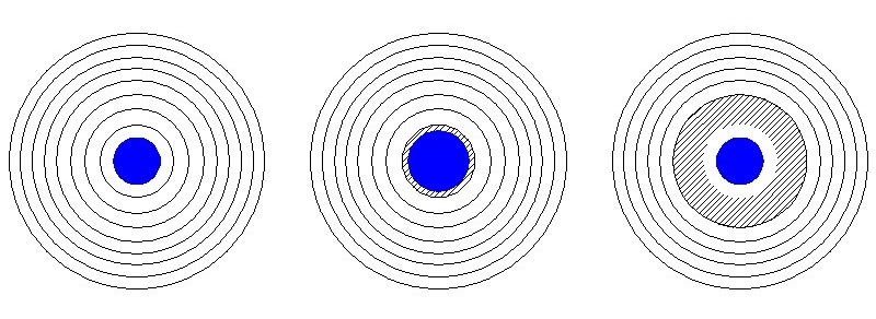
When the sphere increases in volume (from left to centre), it compresses the air in the first surrounding layer (in grey), which in turn compresses the second layer while the sphere returns to its initial size (right).
The inverse phenomenon occurs just after, and again and again...
Now, we can see that the first layer transmits the air pressure variation to the second layer. It is easy to understand that the second will transmit it in turn to the third, etc...
From layer to layer, we can see the increase in pressure, i.e. sound propagates in all directions.
Now, we are aware that the successive layers do not exist in reality, the air being a continuous medium. But the fact is, this is what happens in a continuous way, and it is a well-known model in Physics: reducing the size difference between layers and increasing the number of layers brings us closer and closer to reality. This is done by what is called integral calculus.
Now, looking back at successive layers, we can see that they are getting bigger and bigger according to their rank with respect to the initial sphere. This means that their surface area is also getting larger.
The initial energy of the source remains the same, meaning that the level of successive compressions and expansions will diminish while the distance to the source increases.
This is why the sound level decreases when the distance between the listener and the source increases.
“The most relevant dimension in Acoustics is called the wavelength. It is the distance travelled by a sound wave during one period.”
Knowing that the speed of sound is nearly constant (it only varies a little with the air temperature), one can understand easily that the larger the number of periods per second (or frequency, expressed in Hertz), the smaller the wavelength.
And for once, this relation is linear.
It is expressed as:
λ = c/f
Where λ is the wavelength (in metres or feet, depending on how C is expressed), C is the speed of sound (343 m/second at 20°C) and f is the frequency in Hertz.
Now there is something important to know: anything that is less than λ/4 in size is “invisible” to the sound wave: It has no effect on its propagation.
The consequences are of paramount importance: Reflectors, diffractors and bass traps are all useless if they are smaller than a quarter of a wavelength. They will only have an effect when the frequency is higher (remember: The higher the frequency, the smaller the wavelength)
This is often discouraging to those who expect a “little” acoustic device to have a serious curing effect on room acoustics.
Now, bearing this in mind, we can start to approach Home Theater Acoustics.
When compared to commercial theaters or other auditoria, Home Theater rooms are typically quite small.
The audio frequency range still remains the same, meaning that the acoustic behaviour with respect to the wavelength is very different.
At 20Hz, the wavelength is about 17m. Most Home Theater rooms have all of their 3 dimensions smaller than this value.
However, most rooms have at least one dimension larger than 3.43m corresponding to a frequency of 100Hz.
As one may expect from these two figures, most of the acoustic problems in Home Theater occur between 20Hz and 100Hz, precisely the usual frequency range of subwoofers!
These rooms are designed for playing back a soundtrack that has been processed in a recording/mixing studio, together with the image.
So, what can be considered as the ultimate room is one allowing (provided the whole system is up to the task) the reproduction of the movie soundtrack to be identical to the one the sound engineer listened to in his studio when finalizing his work
In the control room of sound to movie studios, the acoustic properties of the studio are required to be as neutral as possible.
This is what Philip Newell, one of the most famous studio designers, has named Non-Environmental Acoustics – a concept he uses to design control rooms.
Note that this is not the case with the recording areas of studios (generally adjacent to the control room), where some specific ambiances or acoustic “signatures” are deliberately created.
The aim in Home Theater design is to reproduce the same feelings and emotions one can perceive in a commercial theater (Note that the size of studio control rooms is larger than that of Home Theater rooms. It is typically half a commercial theater room, being reduced in depth).
The issue is, because of a very different size, the acoustic problems are quite different.
Typically, a Home Theater room will have:
These phenomena are obviously related to the room dimensions.
We have to be aware that the human ear is capable of differentiating between the first wave front and its various reflections.
Similarly, it is capable of differentiating the very short reflections from the long ones (that is, arriving at the ear with a longer delay vs. the first wave front).
It is easy to understand that very short reflections are more likely to occur in a small space than in a large one. And of course, they provide a very different acoustic signature.
Another issue with very short reflections is that they are not as numerous, having a more discrete character than the long ones that are “averaged”, being a combination of multiple reflections. As they are discrete and have a short delay, short reflections interfere with the initial wave front creating phase cancellations at certain frequencies only, creating what is called “comb-filtering”, as the acoustic spectrum looks a bit like a comb in the high-frequencies.
Needless to say, these short reflections are not welcome in a sound reproduction room.
Experience shows that the reflections that come with a delay shorter than 20 milliseconds after the main wave front are perceived as sound colouration, reducing the intelligibility and the precision of sound localisation.
Reflections arriving with a delay of more than 20 milliseconds are quite acceptable, and are generally so numerous that they become homogeneous: They build together what is called reverberation.
It is acknowledged that the current trend in playback room design is to minimize short (or “early”) reflections, whilst allowing a certain level of reverberation.
Obviously, this is a lot easier in a very large room than in a 30m2 (about 300sq.ft) Home Theater room.
So far, we have seen two challenging design criteria:
Now we will introduce a third criterion: solving the issue of low-frequency standing waves, also called “room modes”.
Here is an illustration of the phenomenon:
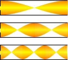
Standing Waves illustration
The above diagram shows the amplitude of waves at certain frequencies, f; f x1.5; f x 2
When a sound hits a hard wall, if it is neither absorbed, nor transmitted, it is reflected backwards.
When travelling backwards into the room, it successively sums with the original sound and cancels it, according to the location with respect to the wavelength.
The above diagram, for simplicity, represents only one dimension. The sound pressure is represented in yellow, with the full height representing the loudest areas.
We can see that the distribution of the sound pressure in the room is going from maximums to zeros, and that the location of the zeros is frequency dependent.
This of course means that the frequency response in one location of the room will be very different from what it will be in any other location.
Now we have a third design criterion:
Well, among the three, this is the most challenging one.
To achieve this goal, there are only 4 solutions. You may think, 4 solutions, it’s not that bad...
But there are severe shortcomings or limitations to these solutions, as you will see.
Achieving solution 1 seems to be the easiest and most sensible approach. It is simple in fact: Make sure that there are no parallel walls facing each other.
This works quite well in the mid and high frequencies. However, the notion of wavelength hits back in low frequencies: If you provide a trapezoidal shape to the room with, say, a 10cm difference in width between one end of the room and the opposite one, then the walls will not appear parallel to the wavelength for frequencies > 857Hz
At lower frequencies, the soundwave will react as if they were parallel.
So, avoiding parallel like behaviour below 100Hz incurs a serious deviation from the typical “shoebox” shape of rooms - or a loss of space.
Solution 2 works fine as long as you do not have immediate neighbours or someone trying to sleep in the next bedroom while you are watching a movie. The low frequencies will go everywhere in the house.
Achieving it is very simple: Use partitions, such as drywalls, that are not made of heavy masonry. Still, this may not be practical, and you may not have the choice. Furthermore light drywalls have some other issues that need to be addressed in acoustic design.
Solution 3 works very well with typical Schroeder – type diffractors, but bearing in mind the wavelength criterion, for such diffractors to be efficient in the 20Hz – 100Hz frequency range they need to be huge.
I once built a diffractor that was large enough. It was 3m deep and occupied the total width and height of the room!
The question is: Can you afford such a loss of space?
Solution 4 is the most practical one. Designing absorption for frequencies <100Hz cannot be achieved with usual absorbing materials (foam, rockwool, etc…) because it would require very thick layers (again of the order of magnitude of a quarter wavelength), but there are acoustic devices like resonators or bass traps that can achieve some absorption without taking half the space of the room.
However, these devices are still very bulky.
There is one solution that does not take too much space and provides very efficient absorption: Active Absorption.
I have worked on two possible solutions involving an active absorption system dedicated to Home Theater Installation, but, please be patient: It will be described in chapter 7.
We can summarize the desired criteria for Home Theater acoustic design:
Now we are provided with a list of criteria and a blank sheet. First, draw the main walls to scale. At least, you cannot be wrong with this.
Next?
Well, here it becomes interesting...
Is to choose where to place the screen, which will obviously determine the position of the audience: Opposite to it.
This step is less obvious than you may think.
Fig 1
Most popular layout
Fig 2
Alternative layout
Both of the above layouts can provide good results. the one thing to pay attention to is you must definitely avoid non-symmetrical implementations.
Having a closer look at Fig.2, instinctively most installers would not choose it. It presents the inconvenience of not maximizing the screen size with respect to the room size. But if the room is large enough, say 8m x 5m, a direct wave from the centre loudspeaker will travel about 4m to reach the audience. The same wave reflecting on the lateral walls will travel about 11.5m to bounce against the surface and return to the audience, that is 7.5m more in distance.
So it will reach the audience with a delay vs. the first wave front of 7.5 x 1000/343 = 21.9 milliseconds.
This already meets one of the principal criteria.
We can therefore leave the sidewalls reflective not to overdamp the room (small diffractors would be needed though to avoid flutter echoes) and treat the other walls with absorbent materials.
Now, looking at Fig .1 for the same room dimensions, we find that for a 4m first wave travel distance, the reflected wave bouncing against the sidewalls has travelled 6.8m, which is 2.8m more.
The delay is then 8.1 milliseconds. If we calculate the delay of the wave bouncing against the rear wall, we find a difference of 4.2m, corresponding to a delay of 12.3ms.
In the case of this room all the walls are providing early reflections <20ms, meaning that all the walls have to be absorbent (this is also valid for the floor and ceiling).
Ideally, in the case of such a layout you will need to:
Absorb all reflections, providing quite a ‘dead’ room environment with a very low RT 60 figure.
Geometrically redirect the early reflections out of the audience (or seating area) towards other reflecting surfaces so that the non-direct waves reach the audience only after multiple reflections have increased the travel time so that the delay is >20ms.
So, although the Fig.2 layout is not the one that is spontaneously adopted by most installers, it has the merit of significantly simplifying the acoustic design. The only drawback is the reduction of the viewing distance and the screen size. This can be an inconvenience if you want as many seats as possible in the room, but this is not always the case.
Consists of solving the problem of standing waves. At medium and high frequencies it is quite easy, just by using diffracting panels or by making non-parallel surfaces. At low frequencies, there are quite a few pre-written spreadsheets allowing you to predict where and at what frequencies standing waves will occur.
Here are a few links:
This is supposed to help positioning the seats so as to minimize standing waves at listening positions.
However, it is not always possible to locate armchairs in a 3D space exactly where the spreadsheet result suggests. In reality, the screen and room dimensions “naturally” define the positions of the chairs:
One will position seats where it makes sense with respect to the viewing angle and the sound system, not the room modes.
The best solution is therefore to absorb the low frequencies that are creating standing waves.
Classical solutions are:
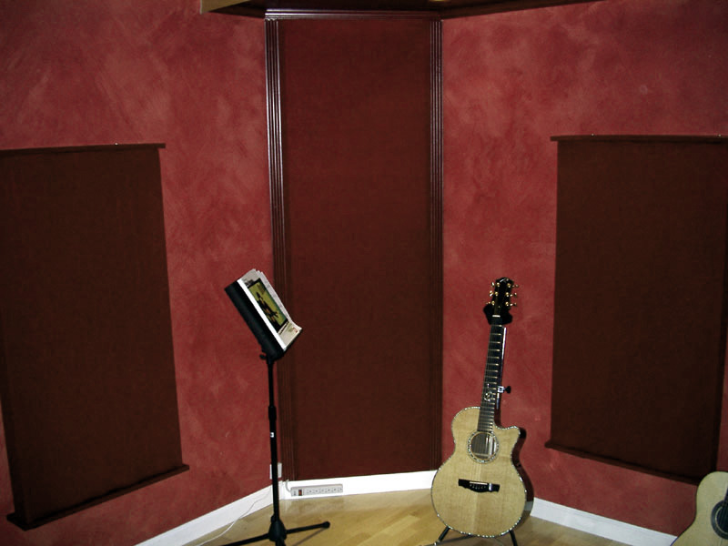
angle bass trap
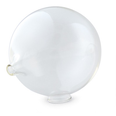
Helmholtz resonator
Bass traps are less absorbent than Helmholtz resonators, but are efficient over a larger frequency range. Resonators (they do not need to have this shape as per the image, don’t worry ;-) ) are very efficient for solving a specific problem at one frequency (or a narrow bandwidth around it). A combination of these two types of devices can effectively solve most of the low-frequency mode problems.
The drawback is that these devices are bulky and not really décor-friendly.
The alternative, as mentioned before, is active absorption.
Is the most creative one. It involves defining how the walls, ceiling and floor will be covered. It may also comprise a step of tough negotiation with an architect or interior designer.
The concept of critical distance
It is generally recommended by acousticians to locate THE listening point (this is already accepting that there is only one!) at the critical distance. This distance is where the level of the direct field equates to the one of the reverberant field, as illustrated below.
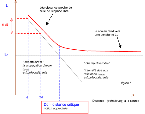
Sorry, this comes from a French document!
This is not a bad idea, but:
There might be more than one row of seats (OK, we can accept that one row is privileged)
The critical distance varies with the reverberation time, which is itself often not constant with frequency, although ideally it should be.
The critical distance is a function of the loudspeaker’s directivity. Although in sound reinforcement, constant directivity is sometimes achieved with very large loudspeakers and only above a certain frequency, residential loudspeakers do not offer constant directivity.
As a result, the critical distance varies with frequency.
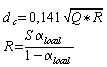
critical distance calculation formula
This frequency dependant characteristic makes this concept unusable in the case of Home Theater
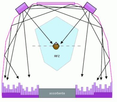
The RFZ concept
RFZ stands for “Reflection Free Zone”, which is an evolution of the LeDe (“Live End-Dead End”) concept, quite popular in studio control room design.
The idea is to design the room geometry in such a way that no discrete short reflection reaches the audience zone, only the direct sound and the reverberation containing reflections >20ms being allowed.
The geometry involves:
Reflecting panels to redirect the early reflected sound waves in a direction that avoids the listening area.
Absorption areas to reduce early reflections that cannot be redirected outside of the audience.
Diffraction surfaces where the reflections will be lagging the direct sound by >20ms.
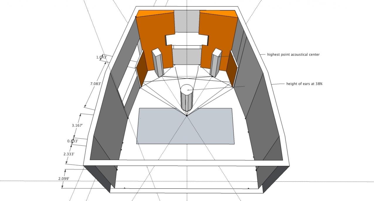
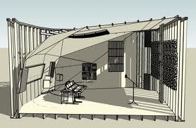
Examples of RFZ designs
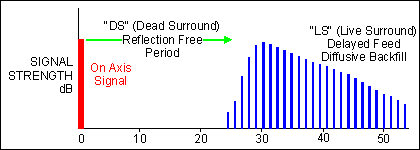
Energy Time curve of an RFZ room
Ideal to meet the second desired criterion, the RFZ concept is not really easy to install, and can be quite costly. It also seriously impacts the room décor. Furthermore, it does not allow one to use the majority of the total room width to install the screen.
As a side note, it is easy to see that the RFZ concept is much easier to implement when using the Fig. 2 layout than the Fig. 1 layout.
Note: the RFZ can only be achieved if there is no reverberant surface very near to the audience. This bans leather armchairs.
The Reverberation Time
It is conventional, to evaluate the Reverberation Time of a room, the measurement is based on what is called the RT60, which is defined by the time the sound takes to decay by 60dB after the source has been shut down.
The longer the RT60, the more reverberant a room is, and vice versa.
The RT60 can be measured, but it can also be predicted.
Sabine’s formula is predominantly used to calculate this:
Concert halls typically have an RT60 comprised between 1.2 second and 2 seconds. Cathedrals can be up to 6s. and public swimming pools and ice-skating arenas can reach >10s.
Commercial theater rooms have typically a (recommended) RT60 of 1 second, normal living rooms are between 0.5 and 0.8 seconds.
Home Theater rooms and recording studio control rooms are ideally between 0.2 and 0.5 seconds, although the latter figure works better for Home Theater.
As most materials have an absorption coefficient that varies with frequency, the proper mix of materials allows the acoustic designer to achieve a nearly constant RT60 at frequencies above 200Hz. At lower frequencies, he will essentially focus on reduction of room modes. With materials ineffective at low frequency absorption (unless used in very large thicknesses), the RT60 will generally be higher below 200Hz.
Positioning the various elements
This is not only Acoustics it is also good common sense.
The 3 front loudspeakers must be behind the screen (which needs to be acoustically transparent, as we have already explained), with the HF transducers at mid-height, at least if the screen is of the WideScreen format (2.35/1 or 2.40/1. This of course also works with the 2.37/1). If the screen is of the HD format (16/9), then the left and right speakers could be located on each side, as near as possible to its edge. The centre loudspeaker must always be behind, at the centre.
The screen should be positioned vertically, such that it can be seen by all members of the audience, but it should not be too high as it is not comfortable to look upwards for the duration of a movie!
When there is more than one row, it is convenient to create a riser for the second row. Using a drawing to represent sight lines is highly recommended.
You can also use the riser as a bass trap, as it is always of a significant volume.
If the RFZ approach is adopted, then the armchairs need to be in this zone. They should preferably not be covered with leather or any reverberant material.
Surround loudspeakers should be above ear level (160 to 200cm from the floor) if the system is of the 5.1 or 7.1 types. For 3D sound systems (Atmos, Auro or DTS-X), they should be placed according to the format specifications.
Finally, it is interesting to use diffraction surfaces at the rear of the room.
Now we can start designing a room and integrating good common sense, practicality and aesthetics.

To be followed soon!