Build the true experience
Chapter 7
Your guide to the true experience in a home theater installation.
Your guide to the true experience in a home theater installation.
Content
This Chapter is the synthesis of all previous chapters, except that it introduces a new concept of my own invention: I have called it The Congard Code. I will avoid complicated formulas to make it an easy-to-read practical guide. This should not only help you to avoid making some common mistakes when designing your Home Theater, but also lead you to excellent results without too many difficulties.
For the most expert amongst you, it will also bring a new approach that you may want to try. Do not hesitate to contact me if you wish to go further, or to have a more in-depth understanding of the involved phenomena.
Finally, I am only considering here what I consider as real Home Theater: Installations with a large passive screen and a video projector. This has nothing to do with TV, whatever the size of the flat screen.
The very first step in a Home Theater design is to select the room. This depends of course on what is available, but some rooms are better suited than others to the installation of a Home Theater.
If a homeowner is asking you to install a Home Theater in a room that is obviously not suitable, you should try to persuade him - after visiting his house, if it is possible - to select another room better suited. If your installation provides poor results, the customer will not be happy and this will never be positive for your reputation either.
Here are some types of rooms that you should definitely avoid:
The most classic type of room is rectangular, nicknamed the 'shoebox'. This can be used easily, but rooms with a trapezoidal shape or with a sloped ceiling can be used too (in that case, the projection axis should be perpendicular to the slope of the roof, to respect the symmetry rule).
All you see when watching a movie in the dark (remember, this is not TV: Your room should be dark when watching a movie!) is the screen. All the sound coming from sounding objects that are visible on the screen come from the screen (behind it, in reality, but they are perceived as coming from the sounding objects).
This is why the right choice of screen is so important. The first thing to choose is the size and the location of the screen. This interacts with the audience distance. Some years ago, when video projector resolution was limited to 800 x 600 pixels, it was a common rule of thumb to place the first row of seats at a distance of 1.6 x the width of the screen. Now with 4K resolution, you can place the first row at 1.2 x W (the screen width), and some clients even want 1.0 x W sometimes.
There is a step that you absolutely need to go through at this stage: A scaled drawing. Skipping that step can only lead to very bad surprises.
Now, when considering how to install your screen and to define its size, bear in mind that the best projection axis is not necessarily the length of the room: In Chapter 6 (room acoustics), I have explained why it can be advantageous to use the width of the room as the projection axis. This is not a golden rule though, but it is easier in a medium size room to achieve a good acoustic design with this layout.
Then, my advice is to choose a screen as large as possible with respect to the audience size, its distance from the screen and the room size; although no seat should have a vision angle of the screen larger than 90° (a larger angle makes it really uncomfortable).
Note: For large angles, it is better to choose curved screens as opposed to flat ones.
For comfort and viewing angles, the screen should not be too high. The base of the screen should be at least at 70 cm from the floor. This means that a screen with a wide aspect ratio (2.35/1 or 2.40/1) can be larger than a screen with a 16/9 TV-type aspect ratio. However, the choice is strongly dependent on the type of program you are watching: If you are watching sports or TV programs, then you should choose 16/9. If you are watching movies, 2.35/1 or 2.40/1 are the obvious choices.
Ideally, and if the budget allows it, screens with motorized masks will avoid the unpleasant grey bars when the image aspect ratio does not match that of the screen
Now, the most important things when choosing a screen:
Since talking movies have been around (1929), placing the centre speaker behind the screen at its centre has been the only accepted layout in commercial cinemas. Now with 3D audio formats being around, from a good precision of sound source localisation previously attained with 7.1 formats, we have now attained extreme precision of moving sounding object localisation.
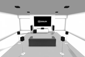
This only works with the loudspeaker layout which sound engineers work with: The 3 front loudspeakers are located behind the screen at median height. This of course requires an A.T. screen.
A.T. screens are either perforated or woven. In commercial cinemas, perforated screens are acceptable because they are large enough, implying a viewing distance where the perforations are not visible (actually, this is not even always the case). Also, perforated screens have a very poor acoustic transparency, with an extremely jagged frequency response, severe loudspeaker directivity alterations and rearward sound wave reflections.
Woven screens have been around for about 12 years now and have proven definitively superior when compared to perforated screens, both in terms of imaging and sound quality. The only shortcoming of woven screens is that they have a gain that is generally lower, typically from 0.8 to 0.95. This is not an issue if your projector is bright enough.

4K is becoming “the” standard now, and screens with a coarse weave can limit the resolution. 4K A.T screens already exist, so you will not need to upgrade when you change your HD projector to a 4K one.
Finally, when choosing a screen, you should bear in mind that it is the most permanent component in a Home Theater installation (the projector being changed most frequently). So you have to make sure you choose the right screen.
The recent evolution of projector technology has been stunning. What would have been regarded as exceptional imaging 5 years ago is not as good as what can be expected from entry-level projectors today. Based on a modern projector, below are the criteria which will really make a difference:
This is what makes a real difference. An excellent projector that is not properly setup will never provide as good an image as an average projector properly calibrated.
Note: A calibrated projector does not provide as many Lumens as when not calibrated. The loss varies with the type of projector, so, when looking at brightness figures, look at the calibrated ones. They are not available in the manufacturer's brochure. Instead, you should look at the test performed here: http://www.projectorcentral.com/.
This is a no-brainer: Go for 4K resolution (also called "Ultra HD"). 8K is still in development as a broadcast standard and your current projector will be worn out by the time this technology reaches residential Home Theaters.
As mentioned in Chapter 1, this depends on the size and the gain of your screen. You should look for a luminance figure of 15 to 18 ft/Lbt (Foot/Lambert), avoiding the higher figures that are stunning for a short demo, but tiresome when watching a whole movie. The calculation is straightforward:
If the projector is not installed in a separate room.
Note: The incredible contrast figures achieved by modern projectors have no real meaning, except that they give a hint of the build quality of the optical part of the projector. The actual contrast is the ratio of the screen luminance vs. its surrounding luminance. If it reaches 1000/1, it is already an exceptional figure.
The sound system is first defined by its format. For the last decade, the 7.1 format has been the most successful in proper Home Theater installations, whereas 5.1 is most popular in complementing a TV screen.
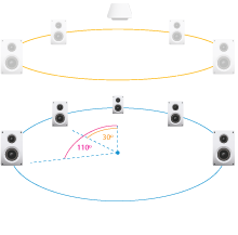
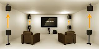
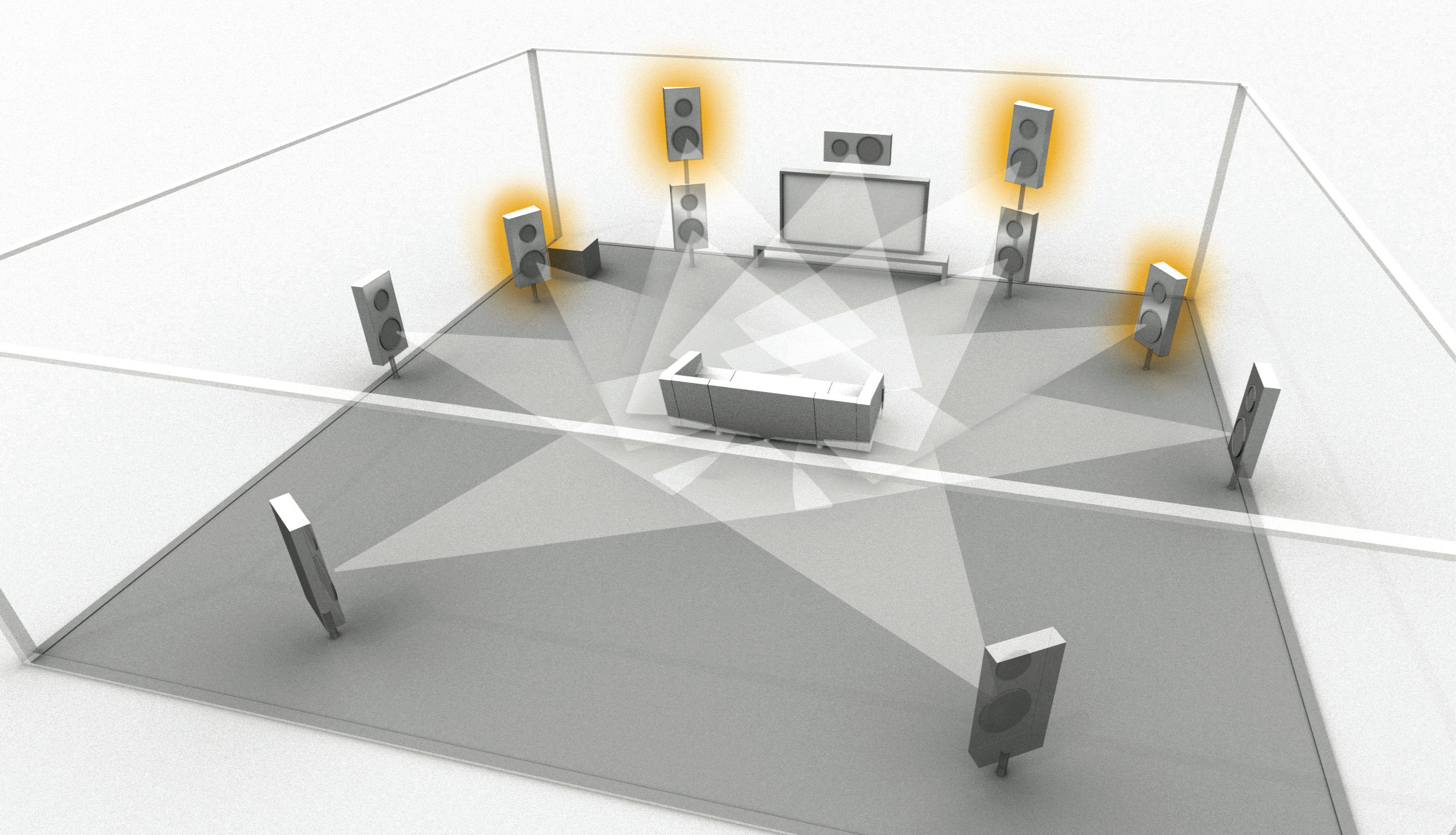
Now we see 3D audio formats as the latest development with, as usual, the hardware being available before the software. For installing a sound system according to any of these formats, there is a need for more loudspeakers, as there are now ceiling speakers that provide the height sounding object localisation, either direct radiating or using ceiling reflections. The main problem is that there are three different competing formats, each of them having different speaker location specifications:
As one can see, the recommended speaker implementations are not the same, so it is not the AV processor or the software that can be automatically reconfigured and swap from one system to another one: We are in a situation of permanently installed and wired loudspeakers.
So, you have to either make a choice between these formats, or add more speakers than necessary for one of these formats to work.Note that all the drawings representing these configurations are provided by the promoters of each of these formats, and that in 2 of the 3 cases they have designed it around a TV screen!
Now, a 3D sound system is not compulsory, you can be satisfied with a “classical” 7.1 installation. However, a 3D sound is not just an added effect: It does provide a sense of immersion and realism that really makes a difference – provided it is installed as it should be. Actually, it is a great leap forward, nearly of the same order as moving from mono to stereo in the old days.
More precisely, a 3D sound system provides an exact positioning of every sounding object, be it visible (that is, on the screen, as the screen defines the field of vision in a proper projection system), or invisible (that is off the screen). With accurate height added to lateral positioning, all sounding objects that are visible MUST have the origin of their sound within the screen, meaning that the screen needs to be acoustically transparent and the L,C,R speakers have to be located behind it. This is something I have mentioned already, but I would emphasise that what is normally needed becomes even more crucial with 3D sound.
Now, back to what has been explained in detail in chapters 2,3 and 4, the choice of the involved components has to be largely determined by the need for a sufficient SPL (Sound Pressure Level) at the average listening position. This should not take into account the reverberant field, as Home Theater rooms are quite ‘dead’ from an acoustic standpoint. This means that each front channel loudspeaker should be able to deliver 105dB easily (a little more headroom is always welcome) at the listening distance, not at 1m!
If a typical listening distance is 4m, then the attenuation versus the SPL at 1m is 12dB. So we would need each loudspeaker to be able to deliver 105 + 12 = 117 dB at 1m. So, for instance, if the loudspeaker has a sensitivity of 90dB/ 1W/1m, it will require 500W to deliver 117dB at 1m, assuming there is no thermal compression (actually, there is some. About 3 to 6dB are lost). If its sensitivity is 95dB / 1W / 1m, then the required power is only 160 Watts.
This means that we need high sensitivity loudspeakers and powerful amplifiers. You should also choose loudspeakers with large dynamic headroom, especially in the high frequencies. Headroom does not mean level, and the HF should never be dominant in the tonal balance! It only means that the HF should be the last transducer to get into its non-linear (understand: heavily distorted) range, and hence, the LF transducer should be the first limiting element of the loudspeaker. Whenever possible, loudspeakers designed with a compression + horn assembly for HF reproduction are the first choice.
Never be afraid to have power amplifiers that can deliver more power than the speakers can handle. Under-rated amplifiers are more likely to destroy loudspeakers than anything else because of highly distorted HF content. So you should choose power amplifiers with a large power rating and large current capability (check the linearity of rated power vs. impedance: Ideally, halving the impedance should double the rated power, which is the case if the voltage output is constant).
Finally, you should always choose separated AV processors and power amplifiers rather than integrated “receivers”. If the budget allows it, use active crossovers and multi-amplification instead of passive designs: Passive crossovers are designed with the drive-unit’s parameters at room temperature. When these units are driven hard, their parameters change with temperature and the crossover’s alignments are no longer valid. When the loudspeakers, like most professional ones, are active or not provided with passive crossovers, you should have a DSP crossover (often called a “speaker manager”) between the AV processor and the power amplifiers if the processor itself does not provide this function. I would recommend a DSP with 24 bit/ 96 kHz A/D and D/A converters rather than a 48kHz model.
Room modes or ‘standing waves’ build up as a result of parallel reflective surfaces facing each other. At mid and high frequency ranges, they are perceived as a “flutter” echo, that is quite disturbing but easy to cure. At low frequencies, above a critical “Schroeder frequency” they are acceptable as their density in the frequency spectrum is such that no particular room mode can be identified as such.
Below the Schroeder frequency, individual room modes are perceived and create position-dependent peaks and dips. in the frequency response.Note that as these irregularities are position-dependent, they cannot be equalized: If you equalize it for one position, it may worsen the response in another one. This Schroeder frequency depends on the room volume (V) and the reverberation time. (T):2000·(T/V)0.5
In Home Theater installations, the Schroeder frequency is most often somewhere between 100 Hz and 200 Hz, so the room modes have a severe effect in the LFE range (20Hz to 120 Hz). A popular approach to smooth out room modes is to use multiple subwoofers in various locations. This indeed provides a much better frequency response, but at the expense of the impact feeling you should get when needed. The reason is that instead of being hit by one strong single wavefront, you are reached by successive waves that are not perceived the way the sound designer intended it. Another way to solve the LF room modes is to diffract them. The problem is: For a diffractor, to be efficient at very low frequencies, it needs to be huge. For example, to be efficient down to 25 Hz, a diffractor has to be 3m deep.
Finally, the best solution for not having room mode problems is to make sure that the waves hitting the walls will not come back into the room. To achieve this, the walls need to let the sound go through to the neighbourhood, or to absorb the LF waves. Absorption is easy to achieve at high frequencies, but at low frequencies it requires very thick absorbing material or specifically designed “bass traps” that are also extremely bulky.
This is an innovative approach I have developed with Anagram Acoustics. The idea is to design the sound system together with the room acoustics and the sound format. Below are the issues this concept addresses:
Classic acoustic design can easily handle higher frequencies with the correct mix of absorption and diffraction. A smart and versatile approach can be achieved with extensive use of heavy absorbent curtains that can also be used to darken a non-dedicated room. Below 100Hz, both absorption and diffraction are typically achieved by the use of very bulky acoustic devices that are likely to eat a large proportion of the available space. Another issue is that Home Theater rooms are typically small compared to the wavelengths in this frequency range. A 20Hz wavelength is 17m long! As a result, discrete standing waves or ‘room modes’ occur, depending on the exact room dimensions.
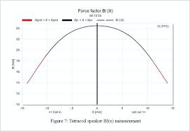
The driving force of a loudspeaker is BL*I, with B being the magnetic flux, L the coil length in the flux, and I the current (supposedly proportional to the voltage delivered by the amplifier. This would be true if the impedance was constant). Now, when the moving coil travels along the magnetic gap, the flux varies, and so does the proportion of the coil in the flux. This of course varies the BL factor becoming, say, B2L2 and results in a force B2L2*I that is no longer equal to the initial BL*I. The deviation of BL from its initial value seriously increases with the distance the coil has moved from its resting position.
It is easy to understand that the smaller the cone displacement, the lower the distortion figure will be. Now, for a given SPL and a given loudspeaker, the cone displacement is proportional to the inverse square of the frequency. In other words, when you divide the frequency by (2), you increase the cone displacement by a factor of (*4).
This really means that there is no phase coherence between these signals, and it is really not a good idea to mix them and feed the same subwoofer with this mixed signal.
How to handle these issues?
The idea is inspired by the vacuum cleaner: When a wave of positive pressure hits a wall, in order to avoid it coming back, it must be compensated by a local negative pressure that will simply suck it out. This is called active absorption and has already been applied in some advanced noise control systems, but not in room mode absorption so far.
The solution is to locate loudspeakers where the density of room modes is at it’s maximum and feed them with a signal that is phase inverted with the arriving wavefront. This can be achieved with two or four subwoofers of a specific design (unlike ordinary subwoofers, the phase response is the dominant design parameter) and adapted signal processing provided by a DSP unit. The original LFE signal and the low frequency content of the L,C,R channels are used and processed accordingly.
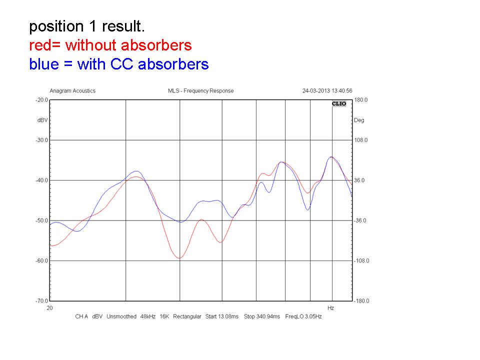
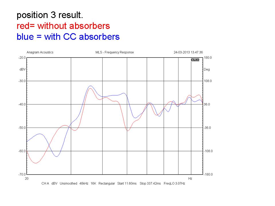
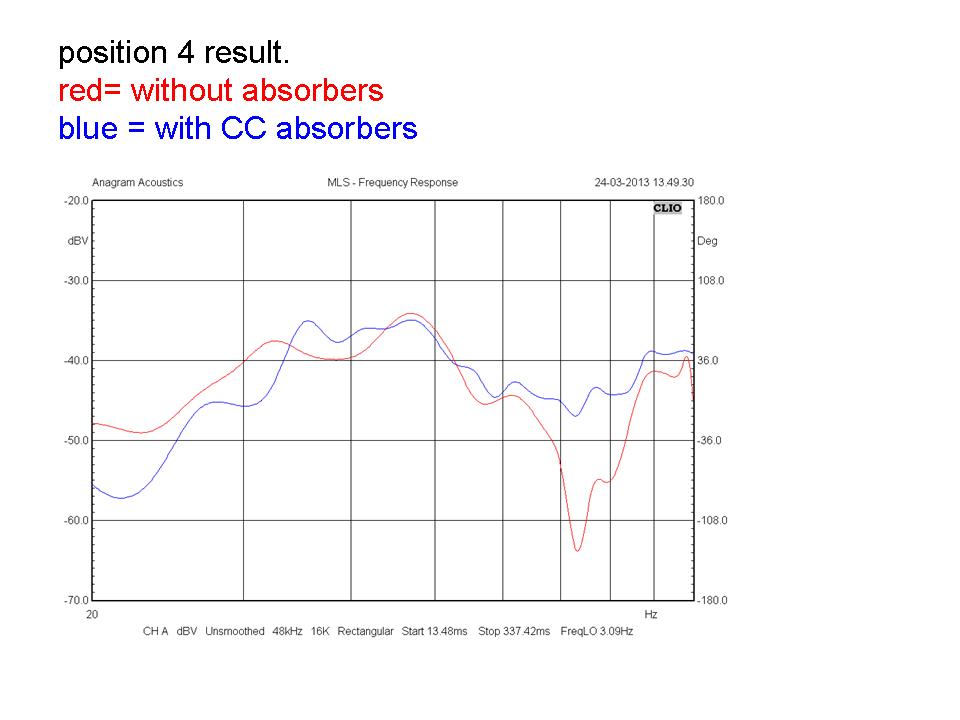
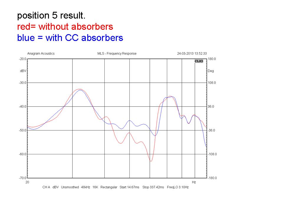
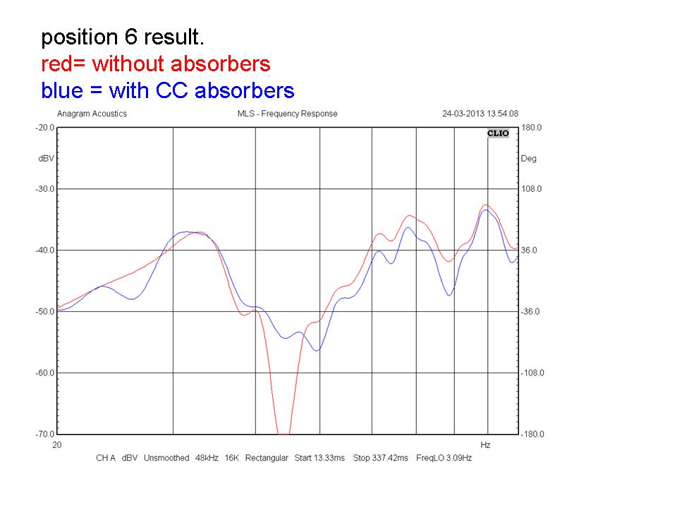
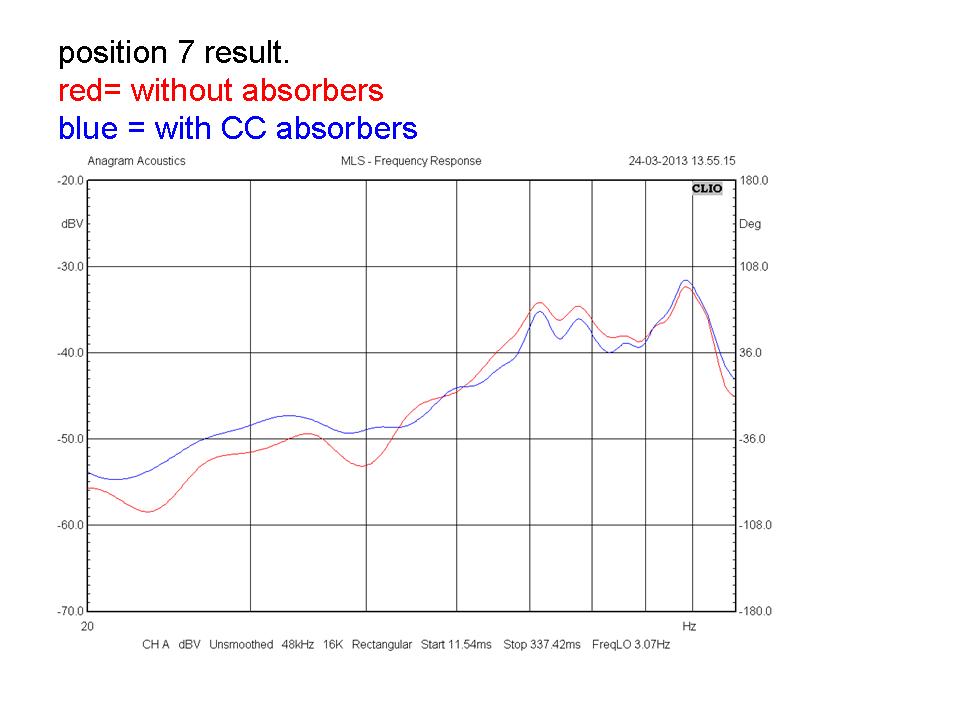
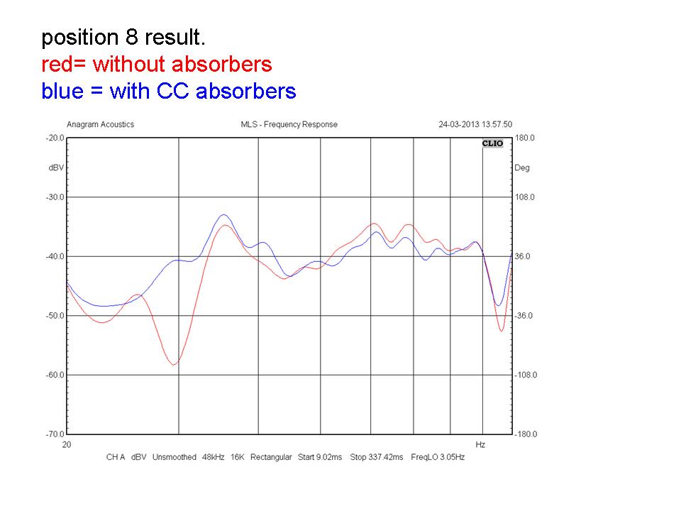
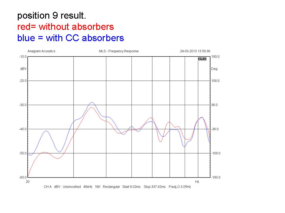
An alternative solution is to use a microphone to capture the wavefront signal, and to shift its phase along the useful bandwidth to transform the pressure into velocity. This will absorb the wave in the corner, where all the room modes are present, for maximum absorption. This can be achieved by means of a pressure-velocity converter like our product ALFAA (Active Low Frequency Acoustic Absorber).
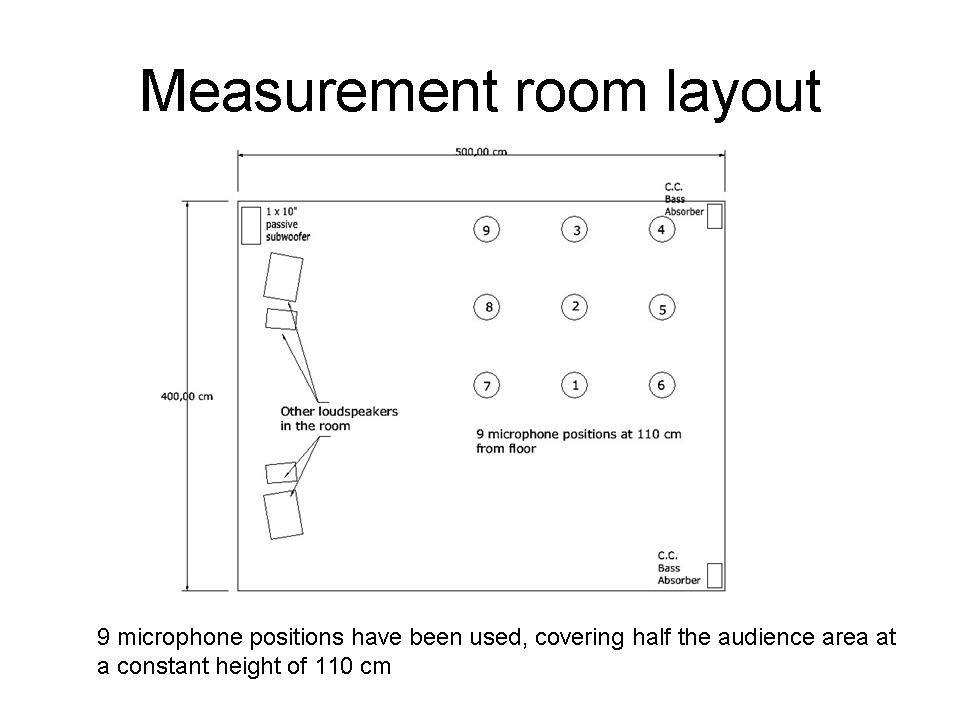
A series of measurements displayed below illustrate the efficiency of this method. For better visibility, the frequency scale is stretched, frequencies between 20Hz and 100Hz covering the whole width of the chart. The results are displayed here:

Looking into paragraph a), it is easy to deduce that there are three ways to reduce cone displacements and hence distortion: One is to reduce the SPL, another one is to reduce the low-frequency extension, and lastly the third one is to increase the surface of the cone. Reducing the SPL is simply not acceptable: It just limits the system performance. Increasing the size of the cone creates some problems in terms of midrange performance, loudspeaker dimensions and cost. Limiting the low frequency extension is perfectly acceptable if there is another way provided to reproduce the missing frequencies: A subwoofer.
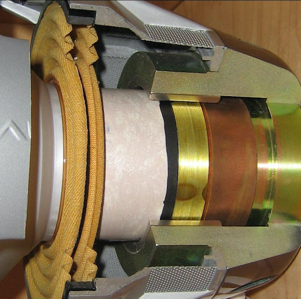
Typically, a subwoofer is designed differently from a wider band loudspeaker as it is dedicated to reproducing frequencies below 100Hz. It has a large cone, a long-excursion motor, and does not generate the distortion level that a typical low-midrange unit would produce when used in the same conditions. Using an active crossover at 100Hz is therefore the most efficient way to reduce loudspeaker distortion. If wide-band loudspeakers can be used in such a way to reproduce frequencies above 100Hz, it is possible to take further advantage of such a setup to use limited-band loudspeakers designed to operate only above 100Hz: Such loudspeakers can be quite loud despite a very small size, and are extremely well damped - a most desirable characteristic.
As I mentioned above, the LFE signal should not be mixed with the front L,C,R signals. It is also preferable to avoid using the typical “Bass Management” systems included in AV processors or receivers, and to set all the speakers in “large” mode. This approach is not critical for the surround nor for the ceiling speakers, as sound engineers tend not to allot any bass content to these channels, knowing that in commercial theater auditoria the surround speakers are much smaller and less powerful than the “screen” front speakers. So, the layout I recommend is this:
There is no inconvenience to this, as there is no localisation cue present below 100 HZ. Furthermore, in a closed space, the ear would not be able to identify its origin. There are some other advantages to such a layout: The position in space of the limited band L,C,R is strictly defined by the screen. These might not be the best locations for positioning LF sources in the room. A single separated subwoofer allows total freedom of positioning, and hence of optimisation.
There is an even better solution, as it cancels axial room modes in one direction (the width) and tangential modes in two directions: Using a subwoofer linear array. This can be achieved by aligning a row of subwoofers with a step of less than 3.4m (the wavelength at 100Hz) that will behave exactly like a single line source. Due to the increased number of transducers, these do not need to be as powerful as a single one. In such a setup, the length axial modes are absorbed by the active absorbers, the width axial modes are simply not generated because of the shape of the initial wavefront, and the height axial modes can either be absorbed by a false ceiling or by an additional couple of active absorbers.
As room modes are no longer present in such a system, we can easily take advantage of the front corners to enhance the LFE subwoofer(s) output.
Various unusual setups and layouts are proposed as a combination to create the concept of The Congard Code (patented). However, all of these are built on physics laws and a no-nonsense approach. They mainly consist of:
Home Theater installations comprise at least 5 remote-controlled devices that are provided with look-alike handsets. A complete home automation system is quite nice to have, but not absolutely necessary. However, a simple integrated system providing all the remote control functions of a Home Theater on one device (preferably a smartphone or a tablet) is something you really need, as struggling with all the various remote sets is a nightmare your client will never forgive you!
If your system can also dim the lights in the room, close motorized curtains, shutters, blinds, whatever, then there is nothing between the audience and the movie they are about to watch. It will not explode the budget, but will double or triple the use of the installation and the customer satisfaction.
What else?