Build the true experience
Chapter 5
Your guide to the true experience in a home theater installation.
Your guide to the true experience in a home theater installation.
To be honest with you, this topic is not always pertinent if installing a showroom. If you are a sensible person, you will choose a location which is not problematic with respect to your neighbours, and which is not in a naturally noisy environment.
I would choose a basement, or the like.
However, you may come across a situation where you have to know about sound insulation.
I also have to warn you: Proper acoustic insulation involves the skills of building engineers or other professional people who don’t necessarily know anything about audio, or sound.
This is scary...
Let me introduce you to the first problem: here are the well-known A, B, C and D weighting curves as used in building acoustics:
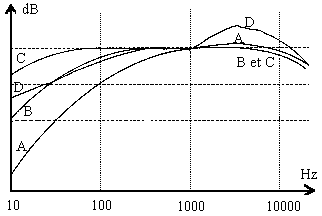
With the values on the Y axis showing the amplitude and the frequency on the X axis
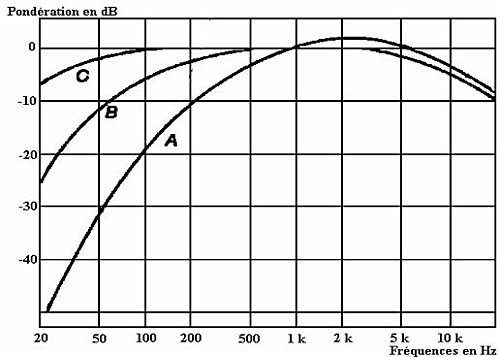
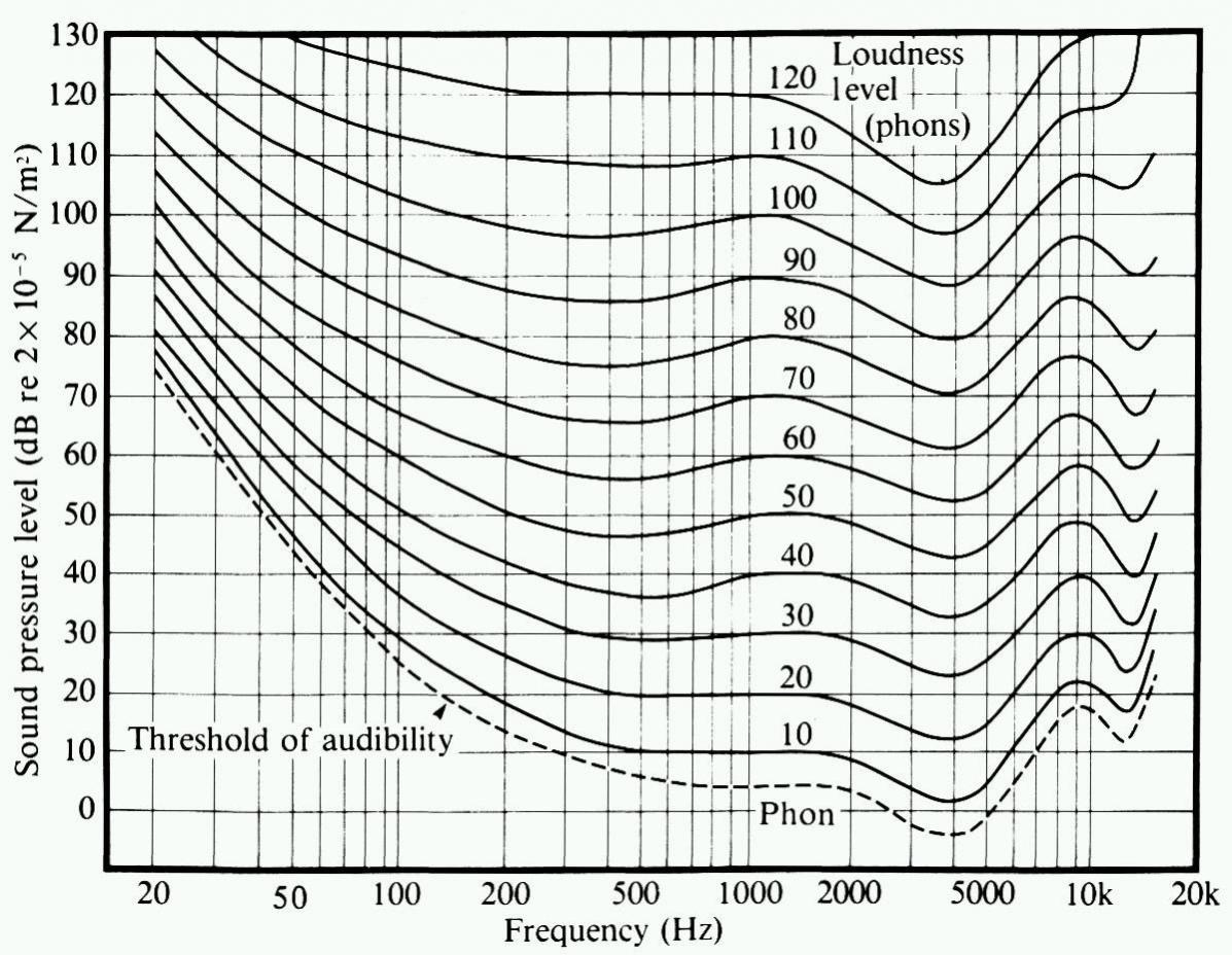
These weighting curves correspond to different criteria, the most common being the ‘A’ curve which resembles the inverse of the human ear sensitivity (Fletcher-Munson curves). This is quite logical as the ‘A’ curve is used for evaluating noise nuisances, so it enhances the frequencies where the ear is the most sensitive.
Back to curve ‘A’, as we can see it puts forward the octave centred around 2 kHz by about +4dB, whereas at 100 Hz it is attenuated by -20 dB and at 20 Hz it is more than 50 dB down.
All right, where am I coming from?
Well, here are two considerations:
This really means that the insulation figures provided by building experts, architects, acousticians and material vendors are not relevant in the case of Home Theater, not giving proper information about what is happening in the most critical 20 Hz-100 Hz range.
For instance, if an acoustic door is said to provide a transmission loss of 60 dB, you should translate “60 dB A’’. This does not give you an idea of what its transmission loss (insulation) is at, say, 50 Hz.
Notice: You can’t even use the A curve to deduce the transmission loss at a given frequency as it is most likely that the door insulation function does not have exactly the same shape as the ‘A’ curve.
In fact, the only way to know the transmission loss of a partition element is to measure it yourself, which is not very easy to perform.
I must admit, this is not good news.
Worse is yet to come...
Insulation is supposed to operate in both directions: from the outside to the inside and the opposite way round. This is not difficult to appreciate, as the partitions are not “semiconductors”.
To isolate a room, you need to understand what is happening in sound transmission through a partition: The sound, being a vibration of the air, hits one side of the partition, pushing it into vibration. Once this partition is vibrating, again it pushes the air into vibration on its other side, hence generating sound.
This involves impedance relations. The partition density being very different from the air, a lot of energy is diverted during this first conversion. Part of it is reflected back into the room, part of it is absorbed (converted into heat). Again, when the opposite side of the partition radiates a vibration into the air it is in contact with, a significant part of the energy is lost because of the density difference.
These losses make the transmission loss of the partition.
Also, like water, the sound tends to sneak into any small leak it can find. If there are acoustic leaks (like a hole, or a pipe going through the partition), the transmission loss of the partition is no longer relevant.

Now let’s look at another problem: if you are trying to prevent sound leakage from one room to an adjacent one, you will first think about insulating their common wall. But the sound in the emitting room can set the ceiling and/or the floor into vibration as well. This vibration can propagate into the building and radiate sound in any room.
Think of your neighbour drilling the masonry at 8:00 a.m. on a Saturday morning… You’ d better live in a detached house.

This problem has been partly solved by acousticians, with ‘’box in the box’’ technology, which is applied in most recording studios. It is quite expensive.
Now, as you may already know, the transmission loss is totally frequency dependent. The lower the frequency, the weaker the insulation.
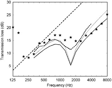
Examples of transmission loss of sound through a partition.
measured results vs. theoretical mass law theoretical result (straight line)
The actual behaviour of a partition is given by the mass law in the low frequency region and by the stiffness law in the high frequency region. These two behaviours are independent functions that meet in an intermediate frequency range in a more or less chaotic way, depending on the material (on the above curve, at about 1600 Hz). The junction between the two functions occurs at a frequency Fc (critical frequency) depending on the nature of the material and on the wall thickness.
Fc = Fc(1 cm) / e with e = wall thickness in cm
Examples of Fc values:
In brief, the sound transmission loss is best when the mass/area is high and the stiffness is high, like in the case of concrete for instance. When you double the thickness of a wall, you double its mass /area figure, improving the transmission loss by 6dB.
Now, if we look at double partitions, things are a bit different.
The losses due to the impedance difference between air and the partition material have 4 occurrences instead of 2. This makes a much better insulation in the mid and high frequencies, and the stiffness law is no longer relevant.
On the figure below, we can see that the curves A and B, corresponding to double partitions, provide much better insulation than the single partition (curve C). Well, generally...
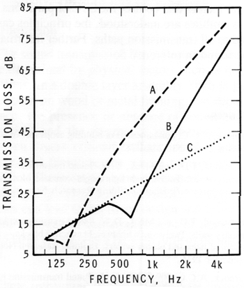
Looking at curve B, we can see a serious loss of insulation at about 700 Hz and looking at curve A, this occurs around 160 Hz.
This is due to a resonance phenomenon, the double mass and the air cavity in between acting like a mass-and-spring system, i.e. a resonator.
Around the resonance frequency, the double partition has a very poor transmission loss, and below this frequency it provides the same figure as the single partition having the same weight.
Now, the ‘’box-in-the-box » concept is exactly this: building double partitions everywhere.
Again, looking at the figure above, the double partition providing the TL of curve ‘A’ provides an exceptional insulation of 65 to 75 dB in the frequency range of 1kHz-4 kHz where the ‘A’ weighting curve is boosted. It will be highly rated for its TL performance. However, around 100 -125 Hz it is the worst of the three curves.
So, why is the double-partition so frequently used in sound recording studios? The answer is simply because recording studios generally are not in locations where they can create nuisances to their neighbourhood. Their main problem is to avoid recording audible noises from external sources in the neighbourhood.
In that case, the ‘A’ weighted curve is relevant.
However, it is not when you are trying to avoid creating nuisances with your subwoofer(s) when playing back a movie soundtrack.
So, what you really need are heavy, stiff single walls.
Low frequency insulation involves masonry works, and is not always feasible. Finally, whether you are adopting the “box-in-box” solution or the blockhaus one, you will need to refresh the air inside. So, this will require an air-conditioning system, which I would like to nickname an “acoustic leak”.
Some air-conditioning specialists have solutions though. They have designed acoustic traps in the ducts, in order to solve sound transmission problems. They can even provide some data - which figures are of course rated in dB ‘A’.
To summarize, sound proofing your HT installation is:
What about a detached house in the countryside?
The next chapter will be more refreshing. It is about the inside of the room...
To be followed soon!