Build the true experience
Chapter 3
Your guide to the true experience in a home theater installation.
Your guide to the true experience in a home theater installation.
After an overview of the SPL needs, we will have a look at the Home Theater sound system configurations.
Many so-called certainties are actually unfounded - the sound domain seems to be the one where this is most common.
A professional approach to sound is often disturbing to the typical Hi-Fi addict.
It only takes a quick read of a so-called “technical” brochure about a loudspeaker to understand how serious the problem is. You will find meaningful words like “transparency”, “bass extension”, “precision”, “fast”, “musical” but nothing that will really help the installer to design a system.
Without the above information, the system designer is left to either do an approximate job, or to perform all these measurements himself. This is particularly critical when matching the loudspeaker to the room’s acoustical environment and the audience geometry.
Such information is compulsory and most commonly provided with professional loudspeakers, as sound engineers simply do not accept working without it. I have to say, strangely enough, I have never found a directivity curve provided with any loudspeaker aimed at the residential market.
Now, if you start believing that such a concept as directivity control has never been considered in the design of residential loudspeakers, I cannot really say that it is 100% true.
Maybe only 99%...
This is not suggesting that most residential loudspeakers are ill-designed, there are a few good choices around. But in many occurrences you will have to pay for a nice veneer or a glossy lacquer whilst your speakers will end up hidden behind a screen.
A Home Theater sound system comprises many more components than a Hi-Fi system, needless to say.
So it is easy to understand why the most demanding customer, willing to use only the best available components for each function of his home cinema will end up postponing the purchase of his new Bugatti Veyron.
For the vast majority of - even affluent - customers, there is a limit to the budget, and hence compromises.
For a start, let’s describe a typical Hi-Fi system. It comprises:
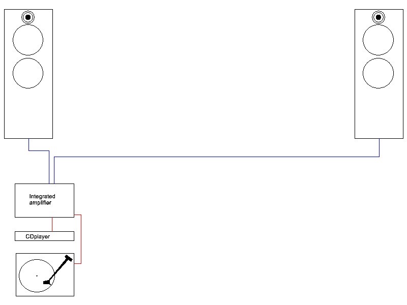
Diagram 1
Now if we describe the audio inventory of a basic Home Theater system, there must be at least:
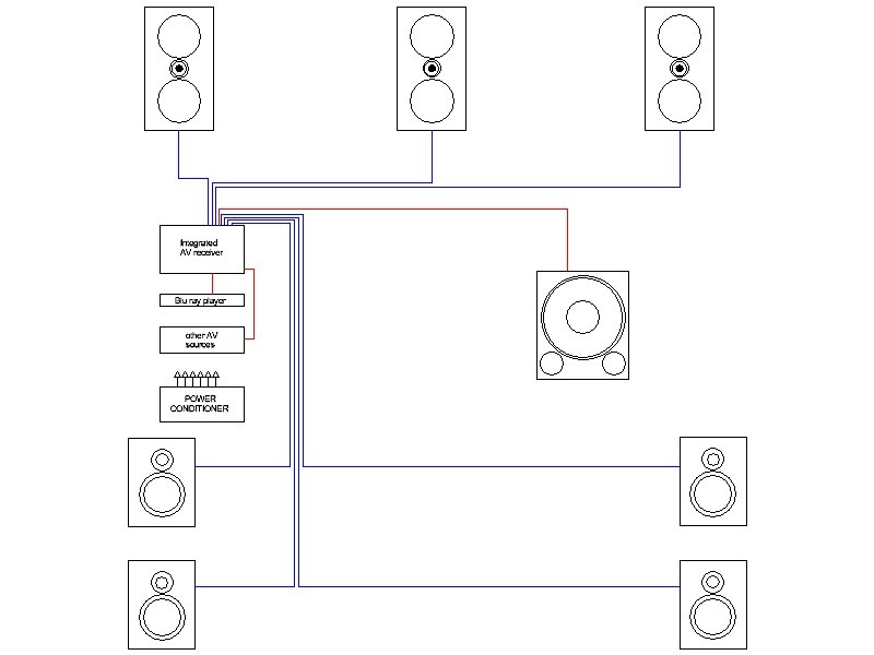
Diagram 2
In a more advanced 7.1 installation, we will find:
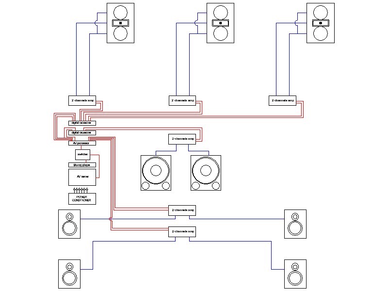
Diagram 3
Now if we want a 3D audio (Dolby Atmos, DTS-X or Auro 3D), we need this:
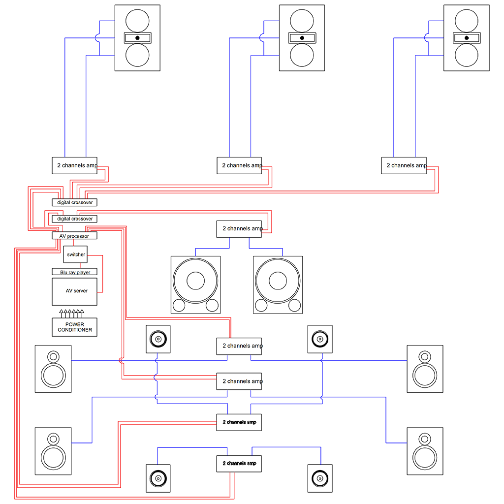
Diagram 4
It is easy to understand how important the cable budget can be, and that esoteric audiophile cables are to be discarded (in addition, their stiffness and diameter can become a nightmare for the installer).
It is also easy to understand that audiophile mono-block valve amplifiers weighing 50kg and rated 40W are not appropriate.
So you will have to forget about spending days doing A/B comparisons between single components or cables.
A HT system needs to be optimised from the perspective of its total budget and practicality, even in “money no object” situations.
In this case, optimisation means balance. Let me get to the point:
It is known that what you hear in a system is its weakest link. Balancing a system means changing the weakest link to a better one, until there is no weakest link at all.
Now, where do you start?
Well, you must have an opinion about component quality.
This is where the image becomes plain white and the sound an unbearable silence…
How do you evaluate the respective quality of the various elements in a complex system as pictured above in diagram 3 or 4?
I’m sure my answer will disappoint most passionate readers of AV magazines: You need professional experience.
If you read tests in the media, you will never find anything that justifies the 1 to 20 price ratio between components which are rated as “excellent”.
So, how are you going to select your components?
Only a tiny minority selects world-renowned brands, top class ranges, and very, very expensive products. These are the customers who will have to postpone the Bugatti Veyron…
More people spend their time on forums. Actually, they don’t need to get involved in HT installation, they do not have time for this as they spend all day on the internet forums (I’m kidding!).
Some rely on 3 letter product certifications, which only prove that their suppliers have paid the flat fee plus the royalties (it’s funny, all certifications have 3 letter labels!)
I would consider the best approach relying on your own experience with the equipment, as you don’t have the time to spend your life testing and comparing components.
However, you need to test a new component from time to time, or you risk becoming outdated.
When designing video systems, things are crystal clear: You choose a screen (an Acoustically Transparent one, but also an Excellent one, preferably) and a projector. After checking their compatibility (lumens vs. dimensions) you then calibrate the projector, play an image and evaluate the result.
Simple!
When designing a sound system, it is far from simple
Any HT sound system involves quite a few components, and the complexity of the system is like an exponential function that has the number of components as exponent.
Also the results are audible instead of visible. This makes a real difference, as the sound, by definition, vanishes immediately whereas a still image can be used for calibration.
There are some measurement methods that are rigorous and reliable, fortunately.
Again, they are better known in the professional domain than in the residential one.
Considering the number and diversity of devices connected to the mains, it is quite difficult, if not impossible, to have a thorough evaluation of the power supply units of each element.
A well-designed power supply will not incur any problem even with a relatively unsteady or polluted mains supply.
However, the performance of many electronic devices, even in the “high-end” range, depends on the quality of the mains supply.
This quality varies with the location of the installation (it is generally better in cities than in the countryside) and with the time of the day.
Therefore, it is wise to be careful about the electrical part of the installation, not only for safety reasons, but also for sound quality.
A few things to do:
As far as 4) is concerned, typical “audiophile“ socket strips do not provide sufficient available power and are sold at a price that can be justified by the amount of silver, gold or complex engineering, but not by the insulation they provide.
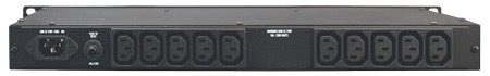
Ideally, the power amplifiers should also be connected to a power conditioner. However, their power consumption requires a very powerful, bulky and expensive power conditioner (see image below). For this reason, such devices are not common in Home Theater installations.
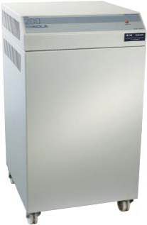
22 KVA mains conditioner
Many audio/video sources provide decent quality at very affordable prices. This does not mean that you should use a Blu-ray player sold at £99.99 to feed a £100,000 installation!
There are typically 3 types of A/V sources:
These devices are the simplest to use and to install. They are also the most affordable ones. Still you need to check:
At the moment, there seems to be a favourite brand among custom installers. You can stick to it
One advantage of HTPC devices is the « all in one » aspect. You can record blu-rays, download video, shortcut lousy legal announcements, get fast access to recorded material, in short, happiness!
But…
Either you are a true geek and configuration problems, compatibility issues etc. are child’s play for you,
And
You know how to feel like Mr. Everybody and design interfaces that even your client’s grandma will find fun to use
Or
You do not have these two skills, and you are heading for a real nightmare.
Audio / Video servers are a bit like HTPC, but they are pre-configured and (nearly) ready to use. They are seemingly the ideal solution, combining a user-friendly interface and a huge storage capacity (count in Terabits).
In fact, most still suffer from two limitations:
So, the remarkable comfort of use associated with these AV servers has a price.
The choice is yours…
For once, this is easy: Since lossless audio formats are available (DTS Master and Dolby True HD), you won’t really feel like listening to anything else (in Home Theater, I mean).
Now that 3D audio formats (Dolby Atmos, DTS-X, Auro 3D) are available, you should choose these. It really brings you nearer to the truth.
So you first need to check that decoders support these formats.
Other things you will need to check are:
Now, if your preamp is provided with an “automatic” equalization function using a measurement device do not worry. All you need to do is to bypass this automatic function.
Anyway, never use it!
We will see why in a further chapter about EQ.
Now that the first elementary requirements are met, what makes a difference between AV pre/pro is the sound quality.
I will not mention the video quality here, as I strongly believe that the video signal of the main source should be connected directly to the video projector. You will need 2 HDMI outputs from your source, as one will be sending the audio signal to the decoder.
Checking the sound quality is something, I believe, you do not need to be advised on.
The amplification of a Home Theater system can be complex, as there are quite a few amplifier channels involved.
The above diagrams #2, #3 and #4 illustrate this. According to the setup on diagram #2, 8 channels are needed, on diagram #3, 12 channels and on diagram # 4, 16 channels.
People used to 2 channel audio may think it is “too much”, but this is only because they are so used to traditional Hi-Fi that they are reluctant to get into the logic of real AV sound systems.
So, rule number one as in scuba diving: never panic!
Looking closely at diagrams #3 and #4, you will see that the 3 front loudspeakers are bi-amped. This means that the HF amplifiers do not necessarily need to be as powerful as the LF ones.
So it is your choice: If you are budget-oriented, you will use less powerful amps for feeding the treble channels and the surround channels, whilst using the most powerful channels for L,C,R bass channels and LFE.
If you are simplicity – oriented, then you will use large power amplifiers throughout.
In the setup pictured in #2, we can choose between 3 types of solutions. The simplest (and most common) one is to use an amplified subwoofer and a 7.1 integrated receiver. However, this does not deliver the best performance.
The 7 channels (usually identical) are supplied by one single power supply, to minimize manufacturing costs. If some of these receivers can offer 7 x 200w, most are limited to 7 x 175 W and oddly enough are offered at more than twice the price of entry-level devices rated 7 x 155 W.
Ain’t that strange?
Looking more closely at these last ones, you will find that the power rating is for a non-standard 6 Ohm load. Even more interesting… Then, you will discover that the rated 155 W per channel is only possible when only 2 channels are in use, but with all channels driven simultaneously, you will only have 7 x 112.63 Watts!
This of course is written in extremely small fonts.
This image is not displaying the virtual AV receiver I have described above.
It just shows that there is one single power supply for all channels.

There is an easy explanation for this: The power supply is designed to provide cost-optimized juice for the two so-called “main” channels (this wording is irritating: there is only one main channel in Home Theater, the centre one). When more channels need power simultaneously, the power supply just gives up.
Pursuing our investigations, we will discover that this magic do-it-all device affords a distortion level which is less than 0.5% and an s/n ratio > 90 dBA.
This kind of figure would be considered not too bad for a 60 year-old single-ended valve amplifier!
Well, it is not, actually.
I am not trying to discourage the thorough and smart attempts of the marketing departments to dissimulate the fact that the receiver is an entry-level, low cost and low performance product by presenting it as a high-end one. The marketing manager job is difficult these days, and I really appreciate their creditable efforts.
Professionals used to nickname an amplifier “black box with gain”. This really gives the right idea of what it is. Or should be.
(I call a single channel an amplifier, for the sake of simplicity)
Its function is to use the electrical energy from the mains to transform an input signal of X Volts in an output signal of X * G Volts, G being the gain.
Professional amplifiers have a normalized value for G, either 26 dB or 32 dB (G=20 and G=40, respectively, as 20 Log 20 = 26 et 20 Log 40 = 32)
This is an ideal world situation.
Please note that X*G is a voltage, not a power.
In the real world, the output signal is: (X Volts * G = X.G + ε1 + ε2 + ε3 +….. εx)
where ε1, ε2, ε3…are harmonic distortion, non-harmonic distortion, noise level, etc.
Here comes the maximum output power.
The X*G product is limited to a definite value (I’ll call it X.G max) which is inherent to the amplifier. When X increases so that the output becomes near to X.G max, G is reduced and ε1 is seriously increased, especially for odd harmonics (the most unpleasant to the ear).
So it seems straightforward to select an amplifier: Maximize X. G max, minimize ε1 + ε2 + ε3.
The larger X. G max, the less likely you are to get near to this limit, which is called clipping level.
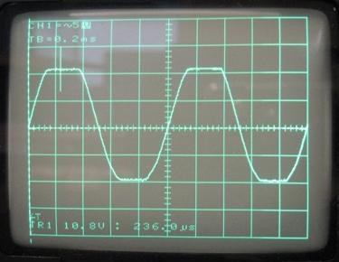
A clipped sinusoïdal signal
In some literature it is stated that some valve amplifiers can sound “louder” than what can be expected from their maximum output. This is supposed to be because their clipping is more “musical” than that of other amplifiers, so you can drive the amplifier harder. Personally, I am very suspicious about the “musicality” of clipping.
This does not mean that amplifiers all sound about the same when they are below clipping level. My point is: I strongly believe that an amplifier that does not clip sounds better than one clipping.
Of course it suggests selecting large power (voltage) amplifiers, which is not the cheapest solution.
Now, let’s look at the power figures, which depend on the load impedance. The impedance of an actual loudspeaker is not a constant, like a resistance, but a function that varies with frequency.
The power figure is given by the Ohm formula: P = U2/R
So, the power P is inversely proportional to the impedance (here expressed as the resistance R). So, if you divide R by 2, you double the power.
The problem here is that G max is, in theory, constant for a given amplifier. In reality, it is only constant within a certain impedance range.
If we look at the figures in the literature, we will see, for instance, an amplifier capable of delivering 200 W into 8 Ohms and 320 W into 4 Ohms.
Applying Ohm’s Law, we will find that the X*G max value is 40V into 8 Ohms, and only 36 V into 4 Ohms. This shows that 4 Ohms is outside of the linear range of X*G max.
Bad news!
Looking at various amplifier’s figures, we will see that for, say, 200 W into 8 Ohms, some amplifiers will deliver 400 W into 4 Ohms (this being ideal), whilst others will only deliver 280 W, for instance.
There are even amplifiers delivering less power into 4 Ohms than into 8 Ohms. This sometimes explains why the power is expressed into a 6 Ohm load: It is the load when the amplifier is at maximum power output. This is being used as a (poor) selling argument.
In some instances, this can be due to the circuit design, but in most cases it is a limitation of the power supply.
The technology of a good power supply is straightforward and well known, so it is not a design issue. It is really a cost issue: In most power amplifiers, the power supply is the main part of the cost (and weight in traditional analogue designs).
So, the trade-off in limiting the cost is limiting the ability of the amplifier to drive low impedance loads.
Well, this does not explain it all.
Nearly everyone knows, amplifiers have different sound qualities. We are in the real world very far from a “black box with gain”.
We can look in detail at ε1 + ε2 + ε3, etc; Beyond a certain level of “decent quality” it will not give us any significant information. If distortion is below 0.01% (-80 dB below signal level) it will not be perceived as it is masked by the sound of the signal itself. Now the noise floor (which does not depend on the signal) will not be audible if the s/n ratio is higher than 100 dB (even with high-efficiency horns). By the way, the s/n ratio is a very interesting indicator of the build quality of the amplifier.
More strange is the significant variation of tonal balance between one amplifier and another, which is never suggested by any frequency response measurement (these are ruler-flat).
Regarding this, I would like to mention a strange experiment I have performed.
I was working in the R&D of professional loudspeakers. Some products in our range still had passive crossovers, and we were setting up a QC measurement of the crossovers.
We used to do it at rather high levels (circa 50 Volts), as they were supposed to be heavy-duty loudspeakers.
We measured the frequency response of the voltage across the crossover load. This is not meaningful but what we were looking for was identical reproduction from one crossover to the other. It was only for QC checks,
In one instance we found results that significantly differed from the standard. Strangely enough, all crossovers in the batch had an identical response, which significantly differed from the previous batch. The implementation was correct, and the components were not different. The only different element was the power amplifier which had been replaced by another one.
We had the surprise to discover that it was very far from ruler-flat, so we thought it was faulty.
Then we re-installed the first amplifier. It had quite a different response, but still far from flat!
Then, we reduced the voltage by steps, and discovered that the curves became nearer and nearer to the ideal straight line when the voltage was reduced. About 10 dB below clipping, the response of both amplifiers had the same straight line.
The most concerning part was the serious divergence of the response at high levels, with deviations of up to 6 dB for the “weakest” of the 2 amplifiers.
I found reassuring that the “weakest” amp was the one which didn’t sound so good….”
It is unfortunate that I did not have the time or later the opportunity to further investigate this experiment, but I did think about it and found a possible explanation, although it is not a verified hypothesis.
It is therefore to be taken with great caution
Looking back at the available power from, for instance, amplifier A:
Whereas amplifier B delivers:
It is easy to understand that at frequencies where the loudspeaker impedance is at its minimum, 4 Ω for instance, amplifier A will have its output voltage limited at a lower value than at frequencies where the impedance is higher. This of course only occurs at high levels when the voltage is near to its maximum.
Still, the result is affecting the frequency response of the amplifier, as the voltage will be higher at some frequencies than at others.
In the same conditions, amplifier B will not have this issue, as it is capable of delivering the same voltage into 4 Ω and into 8 Ω. Its frequency response will remain unchanged.
The serious variation in amplifier frequency response I described above suggests that this limitation phenomenon starts occurring at levels that are far below the clipping level: There would be a progressive modification from the straight ideal response to a load-limited clipped response as the level increases.
It looks like “soft-knee” clipping, which would occur at different levels according to the load impedance and the power supply ability to handle it.
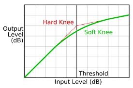
I insist that this is only a hypothesis, I did not investigate this phenomenon deeply enough to derive a definite conclusion. However, this would explain why the tonal balance seems to significantly differ from one power amplifier to another one.
Still, there is no risk to deduce the following preferences when choosing an amplifier:
Well, this has been a bit long, and I just hope you did not fall asleep.
To be followed soon!